ロボットの可視化:URDFとロボットのつながり
Updated on: 2018-02-27
作成したURDFを本物のロボットと繋げてrvizでロボットの状態を可視化します。
rvizとURDFとロボットのつながり
rvizはURDFを表示するとき、/tfトピックで受信したタスクフレームデータを利用してジョイントを正しい位置・角度に合わせてロボットの姿勢を正しく表示します。
/tfに流れているデータはよくrobot_state_publisherというノードで計算されます。
robot_state_publisherは/joint_statesトピックから各ジョイントの位置・角度を受信して、URDFのkinetic treeとあわせて各タスクフレームの位置を計算します。
すなわち、ロボットは/joint_statesに書くジョイントの位置または角度を送信したら、rvizでURDFを利用してロボットの現状の可視化は可能です。
CRANE+ の可視化
manipulator.urdf.xacroを利用してCRANE+をrvizで可視化します。
/tfにデータが流れていてそしてURDFがあれば、可視化は可能です。
ここでmanipulator.urdf.xacroのジョイント名をCRANE+に合わせて、CRANE+のハードウェアを起動して、そしてCRANE+の現状の姿勢をrvizで可視化します。
URDFの変更
URDFのジョイント名とロボットのジョイント名を合わせることが必要です。
下記のようにmanipulator_parts.xacroとone_finger_gripper.xacroのジョイント名を変更します。
-
shoulder_rotate_joint→crane_plus_shoulder_revolute_jointmanipulator_parts.xacroで変更 -
shoulder_pitch_joint→crane_plus_shoulder_flex_jointmanipulator_parts.xacroで変更 -
upper_arm_link_joint→crane_plus_elbow_jointmanipulator_parts.xacroで変更1
<child link="upper_arm_link"/>
上記を下記に変更します。
1
 <child link="crane_plus_elbow"/>
1
2
 <xacro:arm_link link_name="upper_arm_link"
      child_link_name="lower_arm_link"
上記を下記に変更します。
1
2
  <xacro:arm_link link_name="crane_plus_elbow"
      child_link_name="crane_plus_wrist"
-
lower_arm_link_joint→crane_plus_wrist_jointmanipulator_parts.xacroで変更1
<xacro:arm_link link_name="lower_arm_link"
上記を下記に変更します。
1
  <xacro:arm_link link_name="crane_plus_wrist"
-
moving_finger_joint→crane_plus_moving_finger_jointone_finger_gripper.xacroで変更
ワークスペースの準備
CRANE+のハードウェアを利用するためのワークスペースを準備します。
必要なパッケージもインストールします。
そして、ワークスペースチェーニングで自己製のmanipulator_descriptionパッケージも利用可能にします。
まずはMoveIt!とDynamixelのドライバーをyインストールします。
1
2
$ sudo apt-get install ros-kinetic-moveit-*
$ sudo apt-get install ros-kinetic-dynamixel-motor
次に新しいワークスペースを作成します。
1
2
3
4
5
6
$ cd ~/
$ mkdir -p ~/crane_plus_ws/src/
$ cd ~/crane_plus_ws/src/
$ catkin_init_workspace
Creating symlink "~/crane_plus_ws/src/CMakeLists.txt" pointing to
    "/opt/ros/kinetic/share/catkin/cmake/toplevel.cmake"
新しいワークスペースにmanipulator_descriptionパッケージをコピーします。
1
2
$ cd ~/crane_plus_ws/src
$ cp -r ~/urdf_ws/src/manipulator_description .
CRANE+のROSパッケージをダウンロードしワークスペースをコンパイルします。
1
2
3
4
5
6
7
8
9
10
11
12
13
14
15
16
17
18
19
20
$ cd ~/crane_plus_ws/src/
$ git clone https://github.com/gbiggs/crane_plus_arm.git
Cloning into 'crane_plus_arm'...
remote: Counting objects: 474, done.
remote: Total 474 (delta 0), reused 0 (delta 0), pack-reused 474
Receiving objects: 100% (474/474), 1.07 MiB | 1.09 MiB/s, done.
Resolving deltas: 100% (235/235), done.
Checking connectivity... done.
$ cd ~/crane_plus_ws/
$ catkin_make
Base path: ~/crane_plus_ws
Source space: ~/crane_plus_ws/src
Build space: ~/crane_plus_ws/build
Devel space: ~/crane_plus_ws/devel
Install space: ~/crane_plus_ws/install
(省略)
[ 80%] Built target crane_plus_arm_moveit_ikfast_plugin
[100%] Linking CXX executable /home/username/crane_plus_ws/devel/lib/
         crane_plus_camera_calibration/calibrate_camera_checkerboard
[100%] Built target calibrate_camera_checkerboard
下記は新しい端末で実行します。
1
$ source ~/crane_plus_ws/setup.bash
新しい端末を開くたびに上記の実行が必要です。
可視化ようのlaunchファイル作成
CRANE+とrvizを起動するlaunchファイルを作成します。
1
2
$ cd ~/crane_plus_ws
$ touch crane_plus_viz.launch
crane_plus_viz.launchの内容を下記にします。
1
2
3
4
5
6
<launch>
  <param name="robot_description"
    command="$(find xacro)/xacro --inorder '$(find manipulator_description)/urdf/manipulator.urdf.xacro' use_simulation:=false"/>

  <include file="$(find crane_plus_hardware)/launch/start_arm.launch"/>
</launch>
launchファイルはcrane_plus_hardwareパッケージのstart_arm.launchを利用します。
CRANE+のパッケージは、シミュレータとハードウェアは制御インターフェース以外変わらないことを利点にして、シミュレータでもハードウェアでも変わらない実行するノードを再利用可能なlaunchファイルに提供します。
おかげで上記のように別のURDFは簡単に利用できます。
CRANE+のパッケージはシミュレータのURDFを別のパッケージで提供して、シミュレータを起動するためのlaunchファイルでそのURDFを利用します。
ここでは、CRANE+パッケージが提供するURDFの変わりに自己製のURDFを利用します。
ハードウェアを利用するので、use_simulationをfalseにします。
2つの端末を利用してCRANE+とrvizを起動します。
端末1でCRANE+を起動します。
1
2
3
$ cd ~/crane_plus_ws
$ source ~/crane_plus_ws/setup.bash
$ roslaunch crane_plus_viz.launch
端末2でrvizを起動します。
1
2
3
$ cd ~/crane_plus_ws
$ source ~/crane_plus_ws/setup.bash
$ rviz
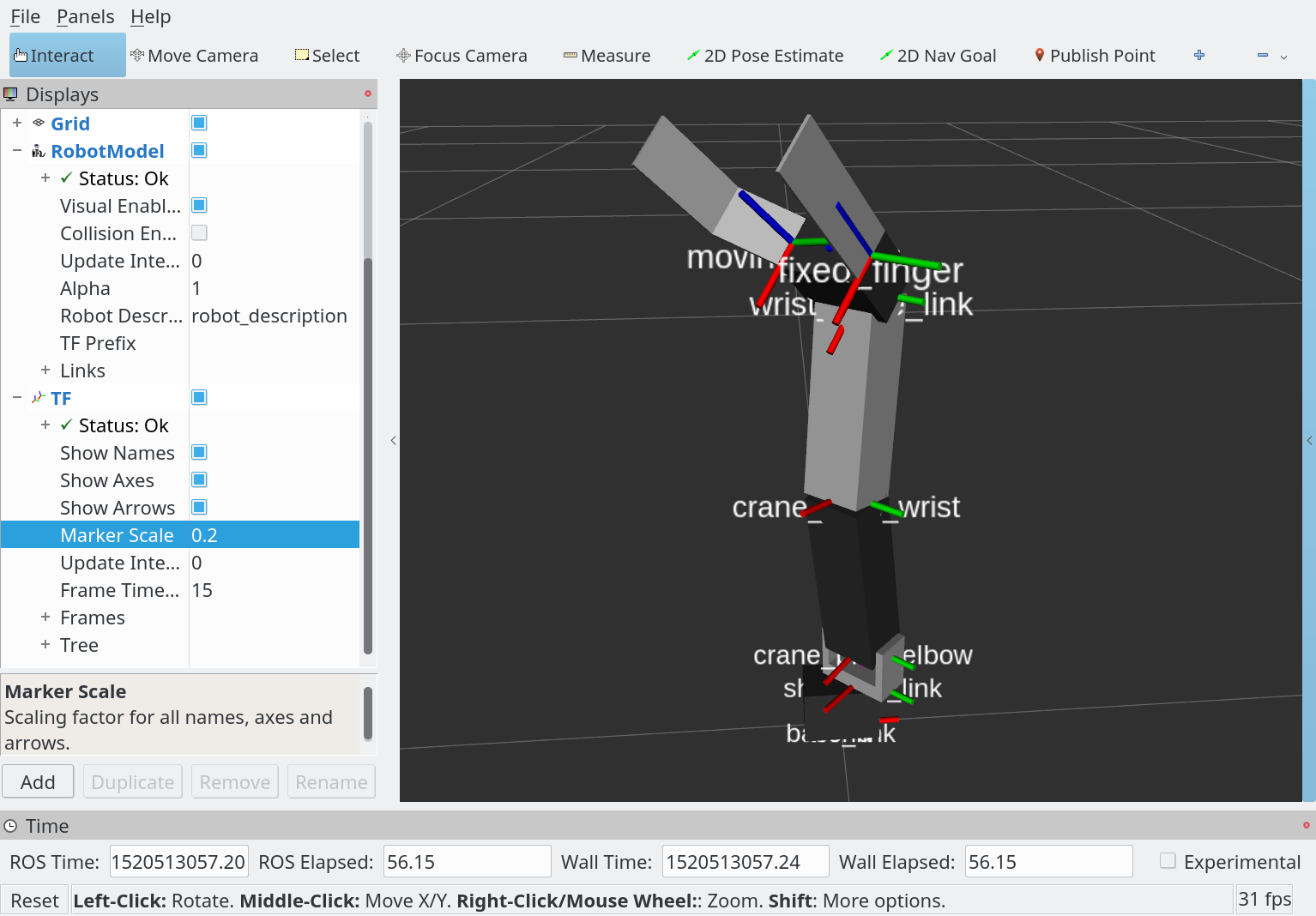
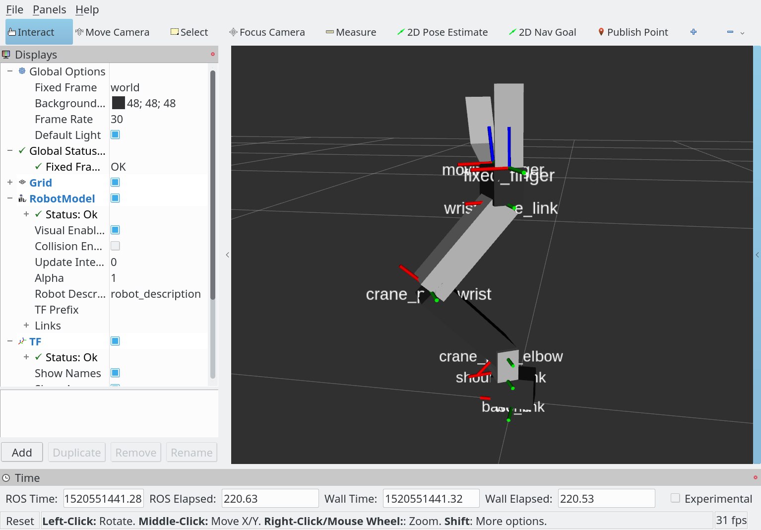
rvizが起動したら、Fixed Frameをbase_linkに変更して、RobotModelとTFの可視化を追加すると下記の図のようにロボットが表示されます。

rostopicでジョイントを制御するとrvizの可視化は本物のロボットと同時に移動します。
1
2
3
4
$ rostopic pub -1 /crane_plus/command trajectory_msgs/JointTrajectory \
  '{joint_names: ["crane_plus_shoulder_revolute_joint", "crane_plus_shoulder_flex_joint", \
  "crane_plus_elbow_joint", "crane_plus_wrist_joint"], \
  points: [{positions: [0.5, -0.75, 1.5, 0.75], time_from_start: [5.0, 0.0]}]}'

URDFのジョイントの舳はCRANE+と逆になっていることはあります。
修正は宿題です。
ヒント:ジョイントのaxisを逆にするとジョイントの動く方向が逆になりながらタスクフレームはそのままです。
このソースは以下のURLでダウンロード可能です。
下記のように自分のワークスペースに入れて利用できます。
1
2
3
4
5
6
$ cd ~/urdf_ws/src
$ git clone https://github.com/gbiggs/rosjp_urdf_tutorial_packages
$ cd rosjp_urdf_tutorial_packages
$ git checkout crane_plus_visualisation
$ cd ~/urdf_ws
$ catkin_make